Understanding Light
What is Light?

<--- Not this Light!
Light is both a particle and a wave. Visible light, which is the light that we can see, is a type of electromagnetic radiation and a transverse wave.
Other forms of electromagnetic radiation include ultraviolet rays, microwaves, and infrared radiation.
Luminous objects emit their own light, such as the Sun (a natural luminous source) or phone screens (artificial luminous sources). Some organisms, like glowing algae, emit light through bioluminescence.
Non-luminous objects do not emit light. They reflect light from luminous objects — such as the Moon or even humans.
Classification of Luminous Objects
Incandescent
These objects produce light due to heat, such as campfires or filament bulbs. They are inefficient because most energy is released as heat rather than light.
Light-Emitting Diodes (LEDs)
LEDs produce light when voltage is applied to semiconductors. They are energy-efficient but have a short lifespan.
Fluorescent Bulbs
These bulbs work when an electric arc excites mercury gas vapours inside the tube, producing ultraviolet radiation. A phosphor coating converts this UV light into visible light.
Mercury ions vibrate at specific frequencies, emitting ultraviolet light. If the bulb breaks, harmful UV radiation and toxic mercury vapours can escape.
High-Intensity Discharge (HID)
HID lights are used in stadiums and streetlights. They operate using an electric arc in a pressurized tube and function similarly to lightning.
Luminescent
These produce light through chemical reactions, such as dashboard lights and bioluminescent animals like jellyfish.
Reflection
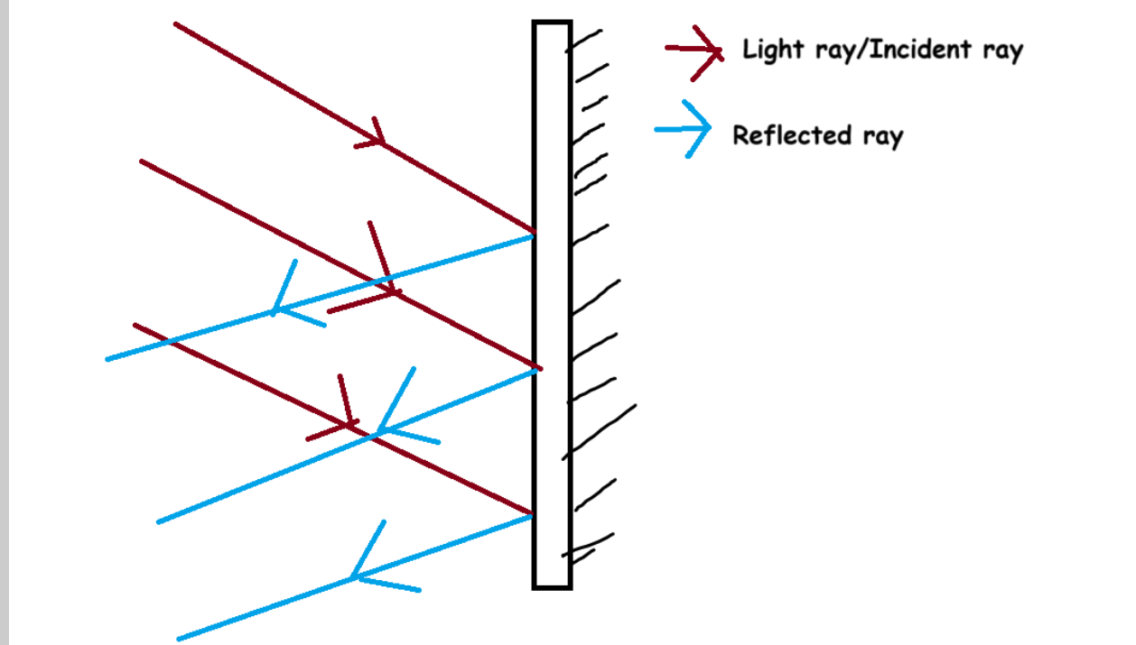
When light encounters a boundary, it can be absorbed, transmitted, or reflected. Reflection is best represented using ray diagrams.
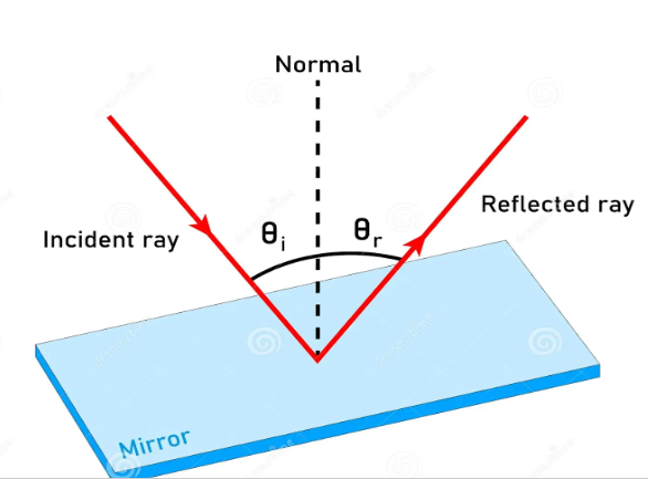
The incident ray strikes the boundary. The normal is an imaginary line perpendicular to the surface. The point where the ray meets the surface is the point of incidence.
Parallel vs Diffuse Reflection
Smooth surfaces cause reflected rays to remain parallel, producing clear images (parallel reflection). Rough surfaces scatter light, producing diffuse reflection.
Experiment: Reflection
Variables
- IV: Angle of incidence
- DV: Angle of reflection
- CV: Wavelength, distance, beam width
Procedure
- Draw horizontal and vertical perpendicular lines.
- Place mirror on the horizontal line.
- Direct the ray to the point of incidence.
- Mark incident and reflected points.
- Measure angles using a protractor.
Errors
Errors may occur due to inaccurate drawing, damaged mirrors, poor marking, or unreadable protractors.
Refraction
Refraction is the bending of light as it passes from one medium to another due to a change in speed.
More dense → Less dense = Faster
Frequency remains constant during refraction, but wavelength changes. Since colour depends on frequency, colour does not change.
Snell’s Law
Snell’s Law relates refractive index and angle of incidence/refraction. It can also be expressed using velocities:
Total Internal Reflection
When light travels from a dense medium to a less dense medium and the angle of incidence exceeds the critical angle, it is reflected back entirely.
This principle is used in fibre optic cables, allowing light to travel long distances without escaping.
Optical Fibres and Endoscopes:
Optical fibres are flexible fibres made from glass or plastic used to transmit light across long distances. They utilize the principle of total internal reflection, as light enters the fibre, is constantly reflected within the medium of glass or plastic, till it escapes the medium when the fibre ends. They are used in fibre-optic communications to transmit information across long distances at high rates or bandwidths.
They are preferred over metal fibres because they are immune to electromagnetic interference and don’t lose as much energy over long distances. These work even if the fibre is bent. They are also thinner than copper wires, meaning you can transmit more information at the same time by packing multiple fibres together.
Compared to satellites, optical fibres are slower but the waves travel less of a distance instead of being sent to the satellite and reflected back. Furthermore, they can’t be interfered with like through storms, unlike satellites.
Optical fibres look like this:
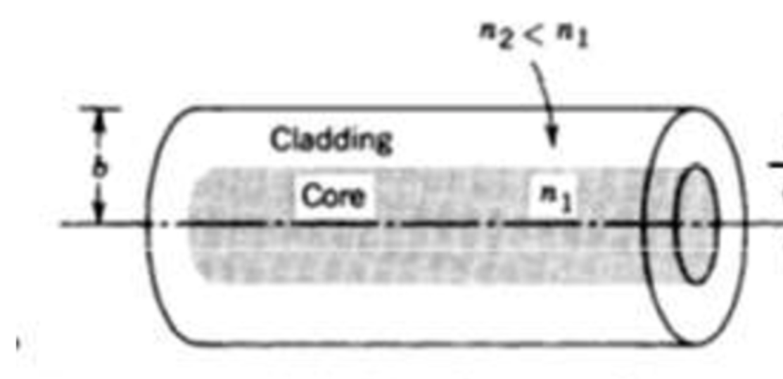
The dark grey thing in the centre is the core, while the lighter cylinder on the outside is the cladding. Both are made from high-purity glass, but the core is denser than the cladding.
Light rays enter through the core. As they move from a medium of high density (the core) to one of low density (the cladding), they undergo total internal reflection and are trapped within the fibre till they reach their destination.
Optical fibres are used in endoscopes and CT scans.
Endoscopes
An endoscope is a device that consists of a bundle of optical fibres that emit light, as well as a camera. The light travels through the optical fibres, reflects off the organs in the body, and is reflected back into the camera lens, giving doctors a clear view of the interior of your body.
This is often used in a procedure called endoscopy, where an endoscope is sent down your mouth and esophagus to check for any abnormalities in the digestive tract.
(Fun fact: I actually had an endoscopy done myself when I was a kid! I remember falling asleep and worrying that I’d feel something going down my throat, and waking up what felt like seconds later, but had actually been an hour or so.)
Another way to get clear images of the inside of the body is through CT scans, or Computerised Tomography scans. These are a series of multiple X-rays done at many angles, which are then either viewed separately or compiled to form a 3D image.
These are often better compared to single X-rays, which only show images from a single angle, where many important structures are often obscured.
Endoscopes are more invasive than CT scans, but they are safer, as they only emit light. CT scans utilize radiation from X-rays, which, in low doses over time, can build up and cause cancer.
However, endoscopes only produce 2D images, whereas CT scans provide both 2D scans and a 3D model.
Mirror, Mirror, On the Wall…

What are mirrors?
These are objects that reflect an image. Normal mirrors are made up of glass coated on one side with a highly reflective material like silver or aluminium.
Plane mirrors are mirrors with flat reflective surfaces, like a 2D plane. The reflection formed in a plane mirror is not distorted.
In ray diagrams, mirrors are drawn in such a way that the smooth side in the diagram is the side with the mirror, and the side with the lines is the back of the mirror.
These mirrors only produce virtual images.
When parallel rays of light hit a plane mirror, the reflected rays are also parallel to each other. The ray diagram for a plane mirror would look something like this:
Properties of images formed by plane mirrors include:
- Laterally inverted: These images are flipped so that the right side of the object becomes the left side of the reflection, and vice-versa.
- Magnification of 1: The image formed in a plane mirror is neither larger than nor smaller than the original size of the obect, meaning it is neither magnified nor diminished.
- Same size: The image formed in a plane mirror is of the same size as the original object.
- Equidistant: The image formed in a plane mirror is at the same distance from the mirror as the original object.
- Virtual: Though the image appears to form at the imaginary point of intersection of the reflected rays, in reality it is formed by diverging reflected rays, making it a virtual image.
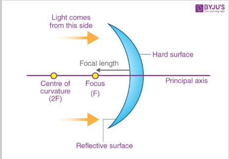
Concave mirrors:
These are one of the two types of spherical mirrors. They look like this:
When an object is viewed from far away in a concave mirror, it is flipped upside down, or inverted. When it is brought closer to the mirror, it goes the right side up, but appears magnified.
When parallel rays of light hit a concave mirror, the rays are focused or converged onto a single point.
Keep in mind, the law of reflection still holds here: if you draw the normals for this, and then measure the angles of incidence and angles of reflection, they would still be the same. However, because the surface is curved, the normals converge towards a single point, and thus, the incidence rays of light are reflected about these normals towards a single point.
Concave mirrors can produce both real and virtual images. They can be used as makeup or dental mirrors due to their enlarging properties in certain cases.
Ray Diagrams for Concave Mirrors + Image Properties:
There are a total of six scenarios where different types of images can be formed onto a screen using a concave mirror.
When drawing a ray diagram for a concave mirror, there are several elements to consider:
The principal axis…
The centre of curvature [C] marks the centre of the circle on whos curvature the concave mirror is modeled. The distance between the centre of curvature and the optic centre is called the radius of curvature.
The focal point (F) is located on the principal axis as the midpoint on the radius of curvature, which is the distance between the centre of curvature and the optic centre.
The optic centre (O) is where the principal axis and the concave mirror intersect.
There are also three basic rules to remember when considering the path of reflected rays:
- Incident rays that are parallel to the principal axis are reflected through the focal point (F).
- Rays that strike the optic centre (O) are reflected back at the same angle. (Essentially, angle of incidence = angle of reflection; there’s nothing special about this ray, but this is its only defining characteristic, so we have to mention it.)
- Incident rays that pass through the focal point (F) are reflected parallel to the principal axis.
Finally, when describing the image formed in each scenario, use the S.A.L.T. strategy:
- Size: Is the image enlarged (bigger than the original object), diminished (smaller than the original object), identical (the same size), or, in special cases, point size or infinitely large?
- Altitude: Is the image inverted (upside down) or non-inverted (right side up)? Images that are formed on the principal axis itself don’t apply here.
- Location: Where is the image formed, relative to points in the diagram? Beyond C? Between C and F? At C?
- Type: Is the image real or virtual?
The six scenarios are as follows:
Object is at infinite distance away from the mirror:
If the object is at an infinite distance from the mirror, the light rays will appear to be parallel. Once again, light rays that are parallel to the principal axis will be reflected through the focal point: all of them.
Size: Point size, as all the rays from different parts of the object are converging at a single point.
Altitude: Formed on the principal axis, so N/A.
Location: Formed at F.
Type: Real.
Object is a finite distance away from the mirror:
As the object is now a practically measurable distance from the mirror, the rays are not all parallel to each other now.
Size: Diminished.
Altitude: Inverted.
Location: Formed between C and F.
Type: Real.
Object is at C:
Size: Identical to the object.
Altitude: Inverted.
Location: Formed at C.
Type: Real.
Object is anywhere between C and F (not just at the midpoint!):
Size: Enlarged.
Altitude: Inveted.
Location: Formed beyond C.
Type: Real.
Object is at F:
When the object is at F, the reflected rays are all parallel to each other. As parallel rays never converge, no image is formed, or the image is formed at infinity. The image will also be infinitely large.
The object is placed between F and O:
At this position, the reflected rays diverge instead of converging, resulting in the formation of a virtual image within the concave mirror.
Size: Enlarged.
Altitude: Non-inverted.
Location: Inside the mirror.
Type: Virtual.
Convex mirrors:
These are the second type of spherical mirrors. Instead of folding in, they bulge outwards.
When an object is viewed in a convex mirror, it’s seen the right side up, but it appears smaller.
Convex mirrors only produce virtual images.
Ray Diagrams for Convex Mirrors + Image Properties
Convex mirrors always diverge rays, meaning they can only produce virtual images.
There are three lines which must be taken into account for convex mirrors:
- A ray that appears to pass through the focal point will be reflected parallel to the principal axis.
- A ray that hits the optic centre will be reflected back at the same angle.
- A ray that is parallel to the principal axis will be reflected back at such an angle that, when extended back, passes through the focal point.
If the image is at an infinite distance away from the mirror:
All the rays appear parallel, so:
Size: Point size.
Altitude: N/A
Location: At focal point
Type: Virtual
Image is any distance away from the mirror:
Size: Diminished.
Altitude: Non-inverted/upright.
Location: Between O and F.
Type: Virtual
Excluding the first exceptional scenario, the distance at which an object is placed from a convex mirror is irrelevant as the properties of the image formed will never change.
Examples of convex mirrors include parking mirrors and car rear view mirrors, as they provide the driver with a greater field of vision. However, images appear to be closer than they actually are due to the fisheye effect from the shape of the mirror.
Mirror Equation:
1/f = 1/v + 1/u
- f = focal length (distance between O and F).
- v = image distance from O.
- u = object distance from O.
If the image is located to the right of O, the x-coordinates will be positive.
If the image is located to the left of O, the x-coordinates will be negative.
If the image is formed below the principal axis, the y-coordinates will be negative.
If the image formed above the principal axis, the y-coordinates will be positive.
The object distance will always be negative because it will be to the left of the mirror.
A negative image distance means the image is real because it is formed in front of the mirror, and is inverted.
A positive image distance means the image is virtual because it is formed behind and inside the mirror, and is upright.
To find the ratio of the image size to the object size, use the formula M = q/p, where:
M = ratio
q = distance of image from mirror
p = distance of object from mirror.
For enlarged images, the M > 1.
For diminished images, the M < 1.
For images of the same size, M = 1.
Real and Virtual Images:
An image is the collection of focus points, or points of convergence, of the light rays coming from or originating from an object. Essentially, wherever rays of light meet, that’s an image.
Real images are formed when reflected light rays converge at a point in front of the mirror. This only occurs in concave mirrors:
As visible here, the rays of light emanating from the arrow, which is the object, are reflected from the concave mirror and converge at a point before diverging again. Even though the light rays diverge later, they do meet at a point in front of the mirror. Therefore, the image formed is a real image, because it comes about as a result of the real convergence of light rays.
Because real images are always formed below the principal axis (the horizontal line in the picture), they will be upside down.
Real images cannot be viewed in the mirror by human eyes. Typically, our eyes can view virtual images because they are formed from diverging rays, which are then converged onto the fovea in the retina by the lens. However, as real images are formed by converging rays, our eyes cannot focus these rays onto the retina, meaning they must be projected onto a screen and then reflected into our eyes for them to be visible.
Virtual images are formed when light rays do not converge at a point in front of the mirror:
The reflected light rays never meet in front of the mirror, but if we trace back their path, they would hypothetically meet behind the mirror. As the light rays appear to converge above the principal axis, the image would be the right side up. Thus, as the light rays never do actually converge, the image formed is a virtual image, because it is formed due to the virtual convergence of light rays.
Convex, concave, and plane mirrors can all produce virtual images.
Magnification:
Magnification, or the ratio of image dimension to object dimension, can be calculated by dividing the image dimension by the object dimension, or:
M = Dimensionimage / Dimensionobject
However, the dimensions being divided must be the same. For example, you can’t divide the height of the reflection by the width of the object.
Lenses:
Concave lenses are wider at the edges and narrower in the middle. They are known as diverging lenses because they diverge rays of light, and form virtual images.
Convex lenses are wider in the middle and narrower at the edge. They are known as converging lenses because they converge rays of light. Equiconvex lenses have the same degree of curvature on both sides.
When drawing ray diagrams for lenses, bring the rays to the middle of the lens before refracting them.
There are three conditions for rays to keep in mind:
- The ray that is parallel to the principal axis passes through the focal point after refraction.
- The ray that passes through the optic centre is not refracted and exits the lens at the same angle.
- The ray that passes through the first focal point becomes parallel to the principal axis after refraction.
The properties of images for convex lenses are the same as that for concave mirrors.
Object is an infinite distance away:
S: Point size.
A: N/A.
L: At F.
T: N/A
Object is beyond C:
S: Diminished
A: Inverted
L: Between C and F
T: Real
Object is at C:
S: Same as object.
A: Inverted.
L: At C.
T: Real.
Object is between C and F:
S: Enlarged
A: Inverted
L: Beyond C
T: Real
Object is at F:
S: Infinitely large.
A: N/A
L: Beyond C
T: N/A
Object is between F and O:
S: Enlarged
A: Upright/Non-inverted
L: Same side as object.
T: Virtual.
For concave lenses, they share their image properties with convex mirrors. Regardless of the position
of the object, the image will always be diminished and virtual.
S: Diminished.
A: Upright/Non-inverted.
L: Between O and F.
T: Virtual.
Lens Equation:
1/f = 1/v - 1/u, where:
- f = focal length
- v = image distance
- u = object distance
Convex lenses are converging lenses, which focus light rays onto the focal point in front of the optic centre. Thus, the focal length for convex lenses is always positive.
Concave lenses are diverging lenses, which cause rays to diverge. Thus, when tracing back the rays, they are found to converge at the focal point before the optic centre. Therefore, the focal length for concave lenses is always negative.
Dispersion of Light:
A single ray of white light consists of multiple rays of light of different colours and wavelengths. When being refracted through a shape like a prism, these rays diverge and are dispersed, forming a rainbow. A similar effect occurs through raindrops.
Red light and blue light have differing wavelengths. Red light has a longer wavelength, whereas blue light has a shorter wavelength. Thus, more waves of blue light interact with the medium per unit of time compared to waves of red light. As waves interact with the medium, they lose energy, causing them to slow down. According to Snell’s Law, the velocity of a wave is directly proportional to its angle of refraction. Thus, slower waves bend less because they refract out of the medium at a smaller angle, while faster waves bend more. This results in individual rays of light being dispersed.
Diffraction:
Diffraction is the bending of a wave around an obstacle. Or through a narrow gap. This can only occur if the obstacle is the same size as the wavelength, meaning a book whose size is in centimeters can’t diffract light whose wavelength is in nanometers.
Diffraction can be observed in solar eclipses, which is why a thin ring of sunlight can be seen surrounding the moon when one occurs.
There are several factors that can affect diffraction, namely:
- Width of the gap: The narrower the width of the gap, the greater the effect on the waves, causing them to spread out more. However, if the width of the gap increases beyond the wave’s wavelength, then the waves will not spread out and the effect of diffraction will no longer be visible.
- Frequency: The greater the frequency of the wave (and as a result, the shorter the wavelength), the less the effect of diffraction. However, the shorter the frequency of the wave, (and the greater the wavelength), the greater the effect of diffraction.
Additive and Subtractive Colour Mixing:
Additive colour mixing occurs when light in three primary colours (red, green, blue) come together, forming white light. “Adding” different amounts of light in different wavelengths (RGB) gives rise to multiple colours. Colours formed by adding two primary colours are called secondary colours.
- R + B = Magenta
- B + G = Cyan
- R + G = Yellow
Subtractive colour mixing occurs when light is absorbed, or “subtracted” when it strikes an object and is reflected back. For example, an apple that appears red only appears red because blue and green wavelengths of light are absorbed by the apple, and red wavelengths are reflected into the observer’s eyes.
If an object is placed in a room where the wavelength of light it reflects isn’t present, the object will appear as a shadow. For example, a red apple placed in a room with only blue light will appear as a shadow, because there is no red light for it to reflect.
If an object is placed in a room where one of the wavelengths of light it reflects is absent, then the object will appear to be the colour of the light that is present. For example, a yellow banana that is placed in a room with only red light will appear red.
According to additive colour mixing, red and green light together make yellow. However, as there is no green light present, only red light is reflected into the person’s eyes, making it appear red.
Myopia, Hypermetropia, and Colour Blindness
Myopia refers to “short-sightedness”, which is when an individual can see objects at a close distance clearly, but objects that are far away appear blurry. This is due to a lengthened eyeball, which causes light to converge ahead of the retina, causing the image to appear unfocused.
This can be corrected through concave lenses, which diverge the rays of light, forcing them to converge further in the eye and land on the retina.
Hypermetropia refers to “long-sightedness”, which is when an individual can see objects at a far distance clearly, but objects that are closer appear blurry. This is due to a shortened eyeball, which causes light to converge beyond the retina, making the image seem blurry.
This can be corrected through convex lenses, which converge rays of light, forcing them to converge sooner in the eye and land on the retina.
Colour blindness is caused by the dysfunction or absence of photoreceptors (cones) in the eye. These photoreceptors fail to appropriately respond to a change in the wavelength of light, which signifies a change in colour.
Unit 2: Energy Resources
Energy Sources : Renewable and Non-renewable, (A & D) Coal fired power stations, wind mill, hydro power stations, nuclear power station, Geothermal, Tidal energy and solar power plants. Solar Cells : Photovoltaic cell and solar panels. Green House gases
Renewable and Non-Renewable Energy Sources
Renewable energy sources provide energy from natural sources that can be replenished quickly over time. These include wind, geothermal, biomass, hydropower, and solar energy. They have several advantages, namely that they can be replenished quickly, making them sustainable; they do not release greenhouse gases into the atmosphere; the construction and maintenance of renewable energy power plants can generate jobs; and they are cost-effective to maintain over time.
However, they have several disadvantages as well, such as that they are reliant on the weather, with solar panels being less efficient in cloudy weather, or wind turbines not being as efficient when wind fails to blow at a certain speed; and require large amounts of space to match the energy output of fossil fuels, namely solar, wind, and hydropower plants. Finally, building these renewable energy plants has a huge upfront cost.
Meanwhile, non-renewable energy sources provide energy from natural sources that are either replenished extremely slowly, or not at all. These include fossil fuels such as coal, oil, and gas, as well as nuclear energy, because the amount of usable radioactive isotopes in the Earth’s crust is finite. On one hand, they have a few advantages, such as they provide large amounts of energy within little space; they are not reliant on the weather.
However, they have several downsides, namely releasing greenhouse gases into the atmosphere, causing air pollution, and producing nuclear waste and increasing the risk of radiation leaks in the case of nuclear energy. Furthermore, the cost of constructing new nuclear power plants is extremely high. Finally, they fail to generate as many jobs as they used to as several of the processes within the power plant are now automated.
Yet a potential solution may have emerged when it comes to the use of fossil fuels that goes by the name of Carbon, Capture, and Storage (CCS), which aims to, you guessed it, capture and store the carbon emissions from fossil fuels underground. However, retrofitting old power plants with CCS technology is costly.
Coal-Fired Power Plants
One of the commonly-used non-renewable energy sources is coal-fired power plants. They look something like this:
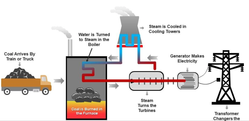
As you can see here, how one of these functions is fairly straightforward.
- Coal is pulverized into tiny pieces for more efficient burning before it is burnt in the furnace.
- Water enters the furnace within a pipe from the boiler, and the heat causes it to boil and change into high-pressure steam.
- The high-pressure steam is forced into a turbine, where it moves the blades of the turbine.
- The mechanical energy of the turbine is converted into electrical energy within the generator. This high-voltage electricity is brought down to a reasonable voltage that can be carried over long distances and supplied to houses by the transformer (not Bumblebee, an actual transformer).
- The steam is condensed back into water, usually through a cooling tower, which removes hot air, bringing down the temperature of the steam, into the atmosphere. This water is recycled back into the boiler.
Solar Power:
When talking about solar power or solar panels, what you’re really talking about is photovoltaic cells. These are structures made of a thin layer of semiconducting material, usually crystallized silicon, sandwiched between two layers of conductors. The silicon layer is made of two different types of silicon: N-type and S-type. The N-type is conducive to the collection and transport of electrons, and so allows electrons to build up within it, making it negatively charged. Meanwhile, the S-type is not very conducive to electrons, instead containing empty spaces for electrons called holes and being positively charged.
When a ray of light strikes the photovoltaic cell, the photons knock electrons from their orbits, leaving behind holes. These newly-delocalized electrons build up in the N-type silicon, and want to travel to the S-type silicon. To do so, they must pass through a cable, and this flow of electrons generates electricity.
The downsides of solar power include:
- Weather dependent: Less energy is produced on cloudy days.
- Location dependent: Certain areas received more sunlight year-round than others.
- Takes up space: To make solar panels efficient, they require a large amount of space for a sufficient amount of them to be installed.
- Inefficient.
Unit 3: Electricity
What is Electricity (B & C) Static Electricity Electrical Charge Current Voltage Resistance Equivalent Resistance Resistivity of Some Materials Ohm’s Law Types of Resistors: Ohmic Resistors Non-Ohmic Resistors Examples of Non Ohmic Resistors: Filament Bulb, Diode, Thermistor, LDR (light dependent resistor) Energy Power Circuit Symbols Electrical Circuits Different types of circuit Series Circuit Current and Voltage in Series Parallel Circuit Current and Voltage in Parallel Combination of Series & Parallel Electronic Circuits and Devices: Voltage Divider, Capacitors, Diode Applications of Diode: Half Wave Rectifier, Full Wave Rectifier Logic Gates Superconductors, Applications of Superconductor: Maglev Train, MRI
Charge, Current, and Voltage
Current is the number of charges flowing through a specific point per second, or, more simply, the rate of flow of charge. If it makes more sense, you can connect it to the concept of cumecs in geography.
While current is depicted as flowing from the positive side of the battery to the negative side, in reality, electrons only flow from the negative side to the positive side. This is due to a historical misconception that it was protons that were responsible for electricity and not electrons, before they figured out that protons couldn’t move because they were trapped in the nucleus.
Even so, it doesn’t really matter– whether you go from positive to negative, or negative to positive, the rate of flow of charge stays the same. Current is measured in amperes or amps, denoted with a capital A. It is measured as Coulombs / second, or charges per second.
Voltage is the amount of energy supplied per unit of charge. Essentially, it is the amount of energy the source (such as a battery) can give to each electron to help it travel from one point to another within a circuit. Another definition for it is the difference in electrical potential energy between two points in a circuit. It is measured in volts, denoted with a capital V, which is through the formula (Joules/Coulombs), to show the joules of electrical energy supplied per unit of charge. The volt is named in honour of Alessandro Volta.
The greater the voltage, the greater the kinetic energy of the electrons and the greater the speed at which they are able to travel. This is why batteries with a greater voltage are used in appliances with longer circuits as electrons need to travel for longer. However, if a high-voltage battery is used in a circuit with a small circuit, then the electrons will gain too much kinetic energy, overheat, and burn the circuit, causing damage.
Furthermore, the greater the voltage supplied, the greater the brightness of any lamps or LEDs connected to the circuit.
Electronic Components
A circuit consists of components connected by wires.
When drawing a circuit, here are the symbols used for each component:
| Component Name | Symbol |
|---|---|
| Battery | 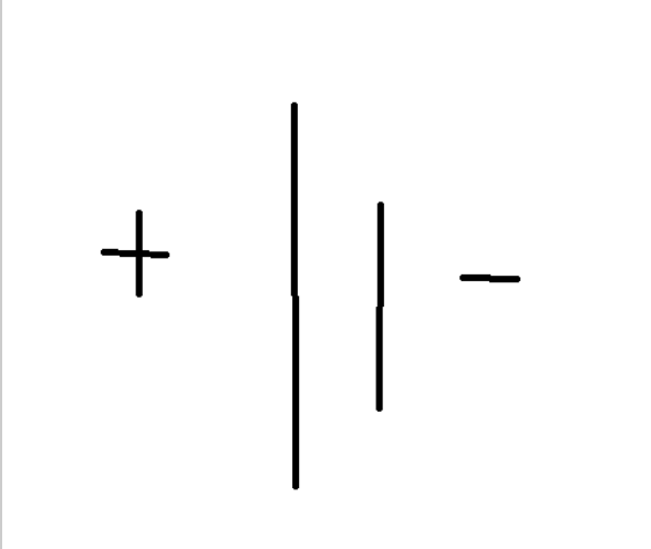 |
| Variable voltage source | 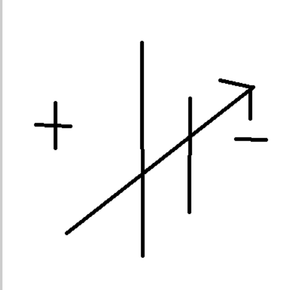 |
| Resistor |  (write the resistance in the box) (write the resistance in the box) |
| Switch | 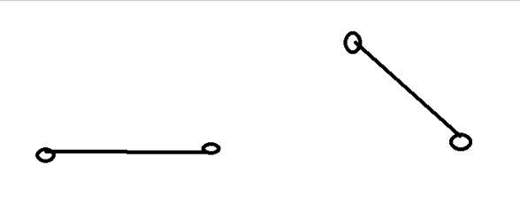 |
| Ammeter | 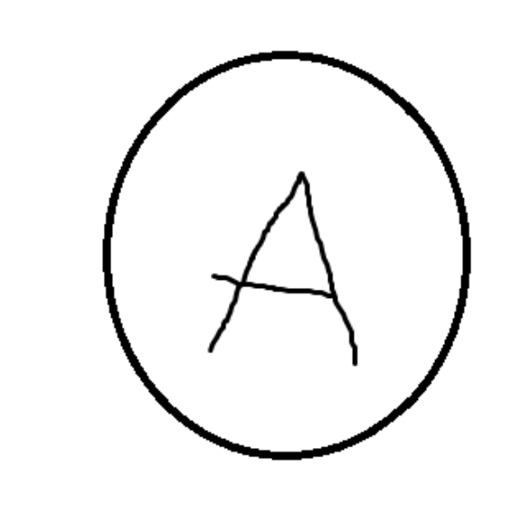 |
| Voltmeter | 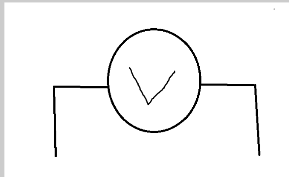 |
| Bulb/Lamp |  |
Parallel and Series Circuits
Parallel and series circuits are both ways to connect components in a circuit. However, parallel circuits possess several advantages over series circuits. Parallel circuits look something like this:
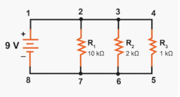
Notice how the components are each separately connected to the power source? That’ll be important later on.
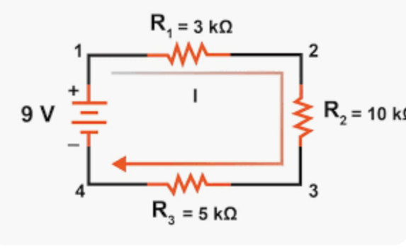
Meanwhile, series circuits look like this:
#1: Control Over Individual Loads
Loads here means components that require electricity to function. These can be fridges in a home as well. Within a parallel circuit, loads can be independently controlled and turned off without affecting other loads. For example, Lamp A can be turned off while Lamp B is turned on.
This is because Lamp B is still getting a supply of power from the source even though Lamp A’s connection is severed as it is turned off.
Meanwhile, in a series circuit, turning off the switch for Lamp A severs the connection to the source for both Lamps A and B, turning both off even if Lamp B should stay on.
#2: Greater Voltage Supplied Per Component/Load
Kirchoff’s First Law of Current states that Itotal = I1 + I2 + I3 …
Kirchoff’s Second Law of Voltage states that Vtotal = V1 + V2 + V3
In a series circuit, the current remains the same throughout the circuit as the electrons have to travel the same distance to reach all the components. However, the voltage is divided among the components, with the components supplied with electricity later down the line receiving less voltage than the first ones connected. This affects the brightness of any lamps connected to the circuit.
In a parallel circuit, the current varies depending on each branch of the circuit as electrons must travel different distances to reach each component. However, the voltage remains the same for each component because they are independently connected to the source individually, and lamps will glow the same.
#3: Less Overall Resistance
Following the formula for resistance, and using the same resistors in each circuit, one for 10 ohms and one for 5 ohms:
Therefore, the overall resistance in the parallel circuit is lower than that of the series circuit.
Resistance
This is the property of the conductor that slows down and opposes the flow of the charge. It occurs because electrons, whose flow is what generates electricity, collide with metal atoms in the wires they travel through, usually copper. As they collide, they lose energy and slow down, generating resistance.
Resistance is indicated with a capital letter R. It is measured in ohms, and can be given by the formula:
R = (ρ × L) / A
- ρ = resistivity
- L = length of the wire
- A = cross-sectional area of the wire
Factors affecting resistance include:
- Length of the wire: The longer the wire, the greater the resistance.
- Cross-sectional area: The wider the wire, the lower the resistance.
Ohm’s Law
Ohm’s Law states that the ratio of voltage and current is equal to the resistance of the resistor:
V / I = R
Current through a resistor is proportional to the potential difference across it. Anything obeying this law is called “ohmic”.
Criterion B & C Experiment
Independent variable: The current through the resistor.
Dependent variable: The voltage across the resistor.
Control variables: Resistance of the resistor, voltage of the source. These must be kept constant to accurately measure the effect of current on voltage.
Method Notes
Always connect the voltmeter at the end. Analog voltmeters must be wired correctly; reversed connections show negative values which can damage the instrument.
Variations on Ohm’s Law
Electrical energy formula: E = V × q
Since I = q / t, we can rewrite as E = V × I × t
Electrical power formula: P = VI
Alternatively:
V = IR
P(e) = VI
P(e) = (IR)I
P(e) = I²R
Notice how here, power is directly proportional to current? This means that this rule holds true when the current is constant, such as in a series circuit, according to Kirchoff’s Law.
Once again:
V = IR
I = V/R
P(e) = VI
P(e) = V(V/R)
P(e) = V²/R
Here, power is directly proportional to voltage, meaning this rule only holds true when the voltage is constant, like in a parallel circuit according to Kirchoff’s Law.
Types of Resistors
Following up to what we just said, resistors can be ohmic, meaning they follow Ohm’s Law, or non-ohmic.
Ohmic resistors have a constant resistance. The only example for this is wires at a constant temperature, as they are the only component that obeys Ohm’s Law. If you apply voltage across a wire at a constant temperature and plot a graph between the voltage and resistance, it will be an ohmic graph.
Non-ohmic resistors have an inconsistent resistance, and they produce a non-ohmic graph. A good example of this is a filament bulb. An increase in voltage speeds up the current, which means more energy is transferred. An increase in overall kinetic energy (the movement of the charges) corresponds to an increase in temperature. Thus, the filament in the bulb heats up and becomes more resistant. This is because as particles in the wire heat up, they start vibrating faster and colliding with electrons more often, increasing the resistance!
Thus, for a certain temperature a filament bulb may obey Ohm’s Law, but as it heats up more and more, it becomes more and more resistant. This produces a curved, non-ohmic graph.
Another good example is a diode.
What is a diode?
A diode is a semiconductor device that allows current only in a single direction. Thus, if you connect the anode of the diode to the anode of the battery, and the cathode to the other cathode, then current can pass through it.
But if you flip it around, and connect the anode of the diode to the cathode of the battery, the current suddenly can’t flow anymore!
Thus, diodes are semiconductors, meaning they only conduct electricity under certain conditions.
This condition for diodes specifically is called forward bias, where it favours the forward connection for current to travel. And its inability to allow current to travel backwards is called reverse bias, where it does not favour a reverse connection.
The arrow symbol in a diode indicates the direction in which the current will flow, and the line indicates that the current will not flow in the other way.
So, if a diode is connected under the conditions for a forward bias, then as the voltage supplied increases, the resistance increases because it remains constant overall. However, if you connect the diode in a reverse bias condition, then the voltage is blocked and is essentially zero. So, because the resistance does NOT stay the same under all conditions, it is a non-ohmic device.
Thermistors: These change their resistance depending on the surrounding temperature. Unlike the filament bulb, if the surrounding temperature increases, the resistance decreases. This also means that resistance is inversely proportional to the surrounding temperature.
Light-dependent resistors (LDRs) change their resistance based on the surrounding light intensity. As light intensity increases, resistance decreases. Once again, resistance is inversely proportional to the surrounding light intensity.
Superconductors
Remember how we spoke about semiconductors? Well, these are on a whole other level.
Take maglev trains, or magnetic levitation trains. They appear to “float” because of two repelling magnets– one on the track, and the other on the bottom of the train. Now, trains (and the people on them) are very heavy, so obviously you need big, powerful magnets. But if you make the magnet bigger, they also get heavier!
And in come electromagnets with the answer. In electromagnets, the strength is directly proportional to the amount of current flowing through it. The more current flowing through it, the stronger it is. So instead of having large, heavy normal magnets, you can simply invest in a good electromagnet and a large battery.
…But a big battery is also costly. And we’re short on cash.
Don’t forget, according to Ohm’s Law, you can increase current by decreasing the resistance, or opposition to the current. Enter superconductors!
Superconductors are materials that can conduct electricity with no resistance once they are cooled to a temperature called the Transition Temperature. This will vary from material to material. These are materials that, theoretically, have zero resistance. In real life, though, they’re less impressive, but they do offer minimal resistance.
Cooling the temperature of a wire to a certain degree will cause atoms to vibrate less and less. Ideally, reaching absolute 0 at 0 Kelvin would mean that all atoms would cease movement, and thus, resistance would be zero. Of course, this is impossible right now. But strangely enough, scientists have found that resistance drops to zero long before reaching absolute zero. This temperature is called the critical temperature.
Going back to the maglev train, with a superconductor, you’d essentially get WAY MORE CURRENT out of the same amount of voltage. And thus, you’d have a stronger magnetic field and have yourself a maglev train.
Electronic Circuits and Devices
Voltage Divider
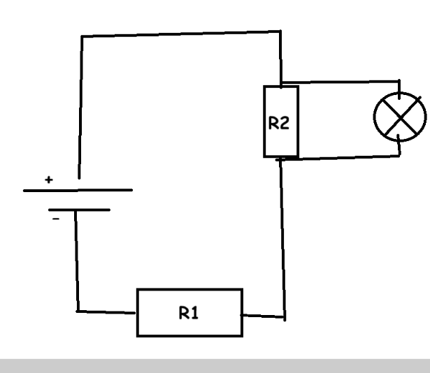
This circuit works on the principle that, in a series circuit, the voltage is gradually divided across each component of the circuit, but the current flowing through the circuit remains the same throughout the circuit.
Thus, if the battery in the picture has a voltage of 9V, then the first resistor will have a voltage of 4.5 V, while the one after that will have one of 4.5V again. But since the lamp is connected to the second resistor in a parallel circuit, voltage will remain the same. Thus, the lamp will receive the same voltage as the resistor it is connected to.
Voltage dividers are useful because they allow you to change the amount of voltage supplied by the same power source to different components without changing the voltage of the power source or the resistance of the component. For example, if we wanted the lamp in the picture to get less voltage, we can just increase the resistance of the first resistor so less voltage is supplied to the second resistor, and by extent, the lamp!
Capacitor
These devices are responsible for storing charge, similar to batteries. However, unlike batteries, which store the electrical energy as chemical energy in the form of a galvanic cell, a capacitor will store electrical energy as electrical energy!
However, this means that capacitors can only store energy for a short period of time, as electrical energy, when stored in that form for longer periods of time, might start to lose energy, compared to being stored in chemical form.
| Capacitor | Battery |
|---|---|
| Stores less charge. | Stores more charge. |
| Charges faster. | Charges slower. |
| Stores energy as electrical energy. | Stores energy as chemical energy. |
Capacitors release stored electrical energy to smooth out any interruptions to the supply of electricity from the battery.
Where are capacitors used?
In a simple circuit with a battery, a switch, and an LED, if you repeatedly turned the switch on and off, the LED would blink, because the direct supply of electricity from the battery is interrupted. But if you added a capacitor, then the LED would remain on, even when the switch is turned off! This is because the capacitor stores and temporarily supplies charge to the LED, even when the battery is turned off/the electricity supply is interrupted.
Another place where it can be used is to smooth out the power supplied by a half-wave rectified AC current. Remember how the current keeps increasing and decreasing? Well, we can add a capacitor to supply stored energy to the circuit while the current decreases and till it increases again.
How do capacitors work?
Picture a 6V battery in a simple circuit with a resistor and a capacitor.
Originally, the voltage, or difference in charge, across both plates of the resistor, is a net 0, because neither plate has been charged yet, and they are both 0. Right now, all that sweet, juicy charge is going straight to the resistor.
However, over time, electrons from the negative end of the battery will flow and accumulate in the negative plate of the capacitor. Both plates are made of conductive material, usually aluminium, separated by a nonconductive material to prevent electrons from flowing between them, which would remove the capacitor’s ability to store charge entirely.
Over time, negative charges from the battery flow to the negative plate of the capacitor and build up there. This continues till the voltage difference between the battery and the capacitor is equal. Remember how the battery had 6V? That means that there is a 6V difference between the battery and the capacitor. Eventually, as the potential difference between the battery and the capacitor is evened out, no more electrons will flow from the battery to the capacitor.
Instead, the electrons in the negative plate of the capacitor will want to flow to the positive one, but they can’t due to the presence of a separating material. Thus, when the capacitor is connected to an appliance or another component, the electrons follow that new path to flow to the positive side. This evens out the potential difference between both plates, meaning no more electrons flow, causing the capacitor to be “discharged”, meaning it needs to be charged by the battery again.
In series circuits
According to Kirchoff’s Laws, in a series circuit, current remains the same across the circuit while voltage reduces because it is shared by all the components. Thus, two capacitors in a series circuit can only have the same charge because they are not isolated. One cannot be drained while the other is fully charged.
In parallel circuits
Remember, according to Kirchoff’s Laws, voltage remains the same across the circuit while the current will vary. Thus, the potential difference across two capacitors in a parallel circuit will remain the same, and the total capacitance (the total amount of energy they can hold) is equal to the sum of the capacitance of both capacitors. If both can hold the same amount of energy, the capacitance is doubled!
Furthermore, because they are isolated, they can have different charges simultaneously. One capacitor can be drained while the other is fully charged.
Diodes
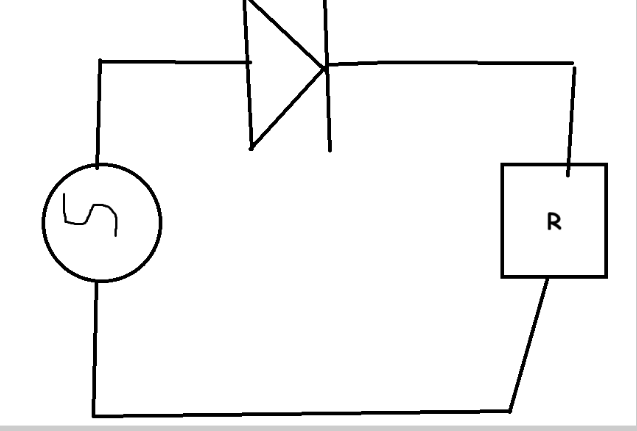
These devices have a wide range of applications, namely as a half-wave rectifier. Rectifiers convert alternating current (AC) into direct current (DC). Alternating current sources are indicated as a circle with a wave/horizontal S-shape in it, as seen in the image, whereas DC sources are shown as a battery.
Alternating current can flow one way for a while, then reverse and flow the other way later, periodically.
Meanwhile, DC only flows one way. If you wanted to flip the current, you’d have to flip the whole battery around.
Thus, if you plot the direction of AC over time, you’d get a waveform that goes above and below a line extending from the origin 0, because the direction of the current changes periodically.
Direct Current (DC) and Half-Wave Rectifiers
Meanwhile, the direction of a direct current over time would remain above the line from the origin. A DC current might vary too, and might appear as a wave, but as long as the wave remains ABOVE the origin line, it is DC, because though a DC current might weaken and slow, or strengthen and increase it can never flow in the opposite direction, and can NEVER take a negative value.
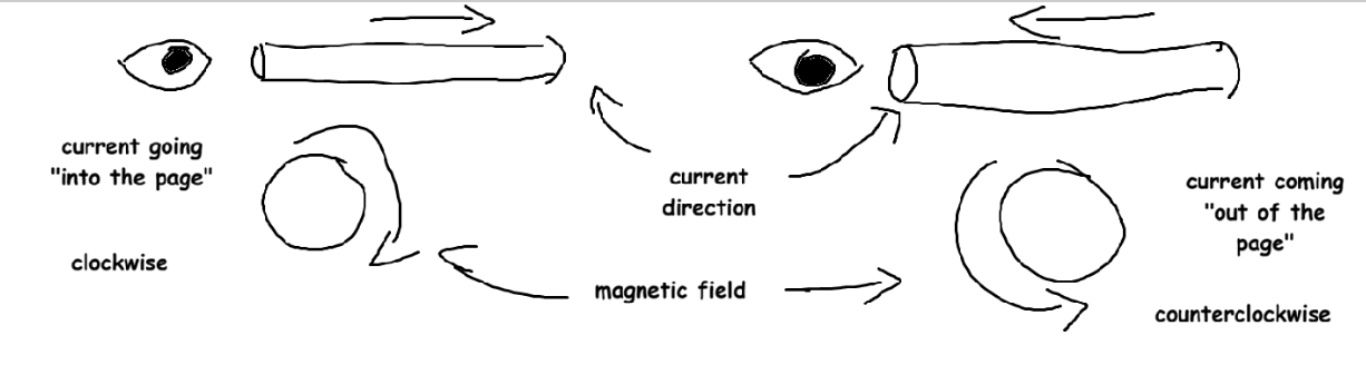
The “positive” and “negative” values indicate whether the current is flowing in the clockwise (positive) or anticlockwise (negative) direction.
Going back to half-wave rectifiers, the part of the AC current flowing in the direction of the forward bias of the diode, essentially the part “above” the origin line, will be allowed to flow through and supply the rest of the circuit with current. However, the other negative half of the AC current that occurs periodically will not be allowed to flow through, because it goes in the opposite direction of the forward bias and will not be allowed to flow through the diode.
It’s called a half-wave rectifier because it only corrects, or rectifies, the “negative half” of the AC. This makes more sense if you plot it on a graph.
Logic Gates
The first thing to understand about logic gates is transistors. These are miniature units within a computer that act as “switches”, switching between on (1) and off (0). This sequence of 1s and 0s is called binary. Each 1 and 0 is a “bit”, and a single transistor can store only 1 bit.
Now, the output of a transistor, which is to say, whether it displays a 1 or a 0, depends on its input and the type of logic gate.
Logic gates are the fundamental components of computer circuits that will accept input and produce an output based on a set of logical rules (hence the word, “logic” gates). There are many types, such as:
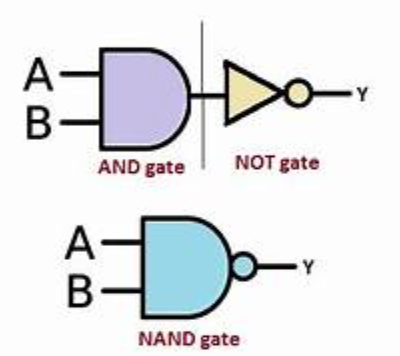
NOT Gate:
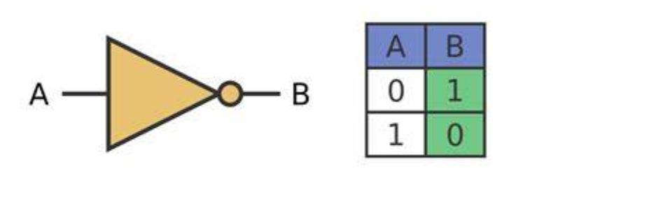
This will produce an output of a value that is not the input. For example, if the input is a 1, the output will be a 0. And if the input is a 0, the output will be a 1. This can be demonstrated in a table called a truth table as seen above.
This looks very similar to a diode, but don’t get confused! Diodes don’t have the circle bit on the end.
AND Gate:
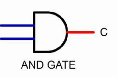
This will only produce an output of 1 if both inputs are 1. For example, if A is 1 and B is 1, then C will be 1. But if A is 1 and B is 0, or vice-versa, then C will only be 0.
| A | B | Output |
|---|---|---|
| 0 | 0 | 0 |
| 0 | 1 | 0 |
| 1 | 0 | 0 |
| 1 | 1 | 1 |
NAND Gate:
This inverts the outputs of a normal AND gate, and functions like if the outputs of an AND gate were passed through a NOR gate.
| A | B | Output |
|---|---|---|
| 1 | 1 | 0 |
| 0 | 0 | 1 |
| 0 | 1 | 1 |
| 1 | 0 | 1 |
Normally, if A and B were 1, then the output would be 1, but since a NAND gate inverts it, it's 0. Similarly, if A were 0 and B were 1, or vice-versa, it would be 0, but again, inversion makes it a 1.
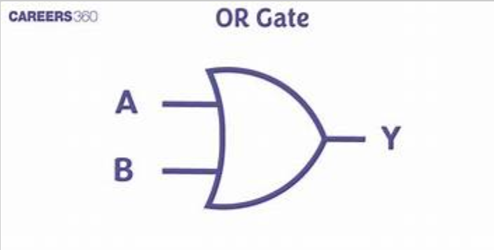
OR Gate:
If A or B is equal to 1, then the output will also be 1! If A and B are both 1, then it will still be equal to 1!
| A | B | Output |
|---|---|---|
| 1 | 0 | 1 |
| 0 | 1 | 1 |
| 1 | 1 | 1 |
| 0 | 0 | 0 |
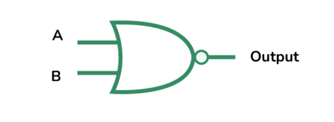
NOR Gate:
This inverts the outputs of a normal OR gate.
| A | B | Output |
|---|---|---|
| 1 | 1 | 0 |
| 1 | 0 | 0 |
| 0 | 1 | 0 |
| 0 | 0 | 1 |
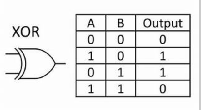
XOR Gate:
This is the “exclusive OR” (XOR) gate, which makes it so that 1 is only displayed EXCLUSIVELY when A OR B has 1, and not when both have 1.
| A | B | Output |
|---|---|---|
| 1 | 0 | 1 |
| 0 | 1 | 1 |
| 1 | 1 | 0 |
| 0 | 0 | 0 |
Magnetic Domains?
You can think of magnetic domains like smaller regions within the material, each made up of God-knows-how-many atoms. Now, the majority of elements on the periodic table have electrons that are paired up and spin in opposite directions, which cancel each other out. However, some elements, namely iron and other metals, have lots of unpaired electrons that can’t cancel their spin out. These will spin in random directions, thus cancelling each other out anyway, but are still unpaired. Keep that in mind.
Now, when an external influence aligns these domains, it forces all the electrons to spin in the same direction, creating what is known as a magnetic domain, and since they are all spinning in a single direction, this creates a distinct direction of flow and allows for the demarcation of “North” and “South” poles, causing ferromagnetism (which is explained later).
The Electrical Method:
This allows for the production of stronger magnets, and involves wrapping a helical coil of wire around a bar of a ferromagnetic material like steel or iron. When there is a current flowing through the coil, a strong magnetic field is generated around the bar. When the current is turned off, the magnetic field disappears.
The setup itself is referred to as a solenoid, which is a type of electromagnet, where magnetic properties are produced thanks to an electric current.
Types of Magnetic Materials:
- Ferromagnetic– These bad boys have tons of unpaired electrons, and are really strongly attracted to magnetic fields. Furthermore, once magnetized, they don’t lose their magnetic properties easily and retain them for a while, even if the external magnetic field is removed.
Ex:- Iron, Nickel, Cobalt. - Paramagnetic– They’re a step down from ferromagnetic materials as they have less unpaired electrons. Thus, they experience a weak attraction to magnets and can be magnetized by an external magnetic field, but when that external influence is removed, they lose these properties.
Ex:- Magnesium, lithium, tantalum. - Diamagnetic– These guys are all the way on the other end of the spectrum. They have little to no unpaired electrons, and experience no attraction to a magnetic field, or even a slight repulsion from it. They can be magnetized, but don’t retain the properties.
Ex:- Gold, copper, silver.
Hard magnetic materials are hard to magnetize, but are even harder to de-magnetize. These are used to make permanent magnets for industrial use. Examples include alloys such as Alcomax and Magnadur.
Soft magnetic materials are easy to magnetize, but lose their properties even more easily, hence they’re used more in electromagnets and transformers. Examples include iron, and Mu-metal, an iron-nickel alloy.
Demagnetization:
Had enough of the old magnet? Well, to de-magnetize it, you need to disrupt the alignment of the magnetic domains, and this can be done in two ways:
- Heat it! Heating the magnet excites the atoms and electrons, pushing the domains out of alignment.
- Hit it! The sheer force, either by dropping it or hammering it, disrupts the magnetic domains.
Electromagnetism?
You don’t have to be a genius to put two and two together at this point and guess that electricity and magnetism are somehow interconnected with each other. And that brings us to electromagnetism. Put simply, electromagnetism is the magnetic effect of current.
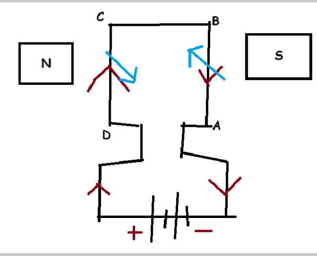
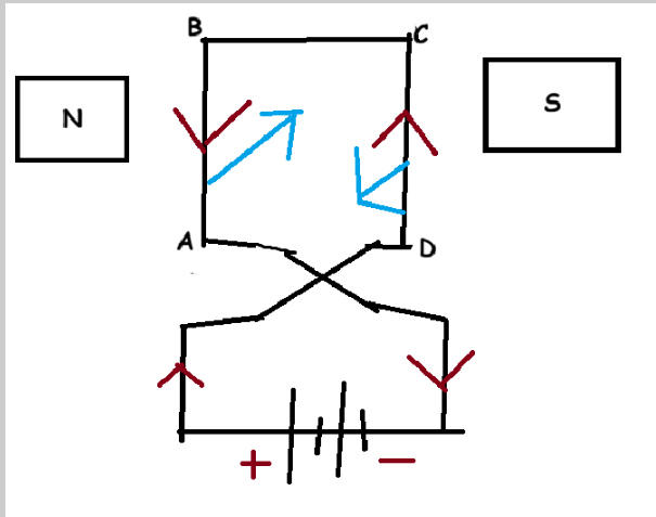
Also, reversing the current reverses the direction of the magnetic field!
The Electromagnetic field, how Electric and Magnetic forces arise
The following notes are basically paraphrasing what these two amazing videos said:
Now, electromagnetism is a bit more complicated than it seems. Take, for example, motion and time. According to a branch of physics called special relativity, they vary depending on your frame of reference!
- An object in motion will contract in its direction of motion ever so slightly.
- Time passes slower for observers moving relative to you.
Now, let’s picture a wire made of, say, copper.
On its own, copper is NOT a magnetic material. But turned into a solenoid, it can form a pretty good electromagnet. And here’s why:
Thanks to metallic bonding, in a copper wire, you’ve got positive ions bouncing around with negative electrons that are freely moving. Now, if you make an electric current flow through the wire, the electrons are going to drift in one direction while the protons are unaffected. However, the density of protons and electrons are the same, creating an overall neutral wire with no positive or negative charge.
Now, let’s say we bring in a positively-charged particle. Not a proton, but just a particle that has a positive charge. When stationary, it isn’t attracted or repelled by the neutral wire.
However, if the particle starts moving in the same direction and velocity as the electrons, things start to change. Now that the positive particle and the electrons are moving at the same pace in the same direction, if we look at things from the positive particle’s point of view, the protons are actually the ones that are moving!
If you’re confused, picture yourself inside a moving train. From inside the train, the trees appear to move while you and the train are stationary, even though the train is moving and taking you with it.
Now, remember that objects moving in their direction of motion contract slightly, so the electrons contract. And thus, relative to these electrons, objects that are stationary take up more space, so the protons could expand. Now, there’s a greater density of protons than electrons, meaning the wire has a positive charge and repels the positive particle.
Now, from our point of view, what we see is a particle being repelled by a neutral wire. But from the particle’s point of view, it gets repelled by a positively-charged wire. This phenomenon is called electromagnetism because, while an electric field can exist with both static and moving charges, a magnetic field can only be formed in the presence of moving charges.
Electromagnets:
One of the most common types of electromagnets out there are solenoids. They are much stronger than your average old bar or disc magnet, and can be turned on and off with the flick of a switch!
To increase the strength of an electromagnet, you can either increase the current flowing through the wire, or increase the number of turns!
Furthermore, the magnetic field generated by the wire magnetizes the core, creating an even stronger magnetic field. However, only a soft magnetic material can be used for the core, as a hard one would become permanently magnetized.
Applications of Electromagnets:
Magnetic Relay
A relay is an electrically-operated switch, compared to normal switches, which you flick on and off with your hands. Another thing that makes them so distinctive is that they only need a small electrical signal to function, but can turn on or turn off high-current or high-voltage circuits, which makes them safer for humans to use. Furthermore, it uses an armature controlled by an electromagnet to turn off the dangerous circuit it controls without being directly electrically connected by wires.
How do they Work?
How do relays work? - Explain that Stuff!
Relays can function for two purposes: switches or amplifiers.
Switches?
These relays come in two types: Normally Open (NO) and Normally Closed (NC). How they work is simple. When power flows through the relay, the electromagnet is activated, generating a magnetic field around it. It attracts the contact towards it, making it close and complete the circuit and allowing power to flow through.
You will, however, notice that the contact is also connected to a spring! This is so that, when the power is turned off and the electromagnet stops produce a magnetic field, the contact is no longer attracted and instead, the spring pulls it back to its original position, opening the circuit and preventing power from flowing through, acting as a switch. This is an NO circuit, as it is normally open but only closes when the electromagnet is activated. NC circuits are vice-versa, where the circuit is normally closed till an electromagnet attracts it.
Amplifiers?
These are basically the same as switches, but in a different font. In amplifier setups, the original circuit connecting the power source and the relay is closed and the electromagnet is activated, either by a sensor or by manual touch. This, in turn, attracts the contact on the higher-voltage/higher-current circuit, closing it and completing it. Thus, a low-energy input provides a high-energy output.
Circuit Breaker
These bad boys are electrical safety devices. Their job is to protect electrical circuits from being damaged when there is an excess of current beyond its maximum capacity, which could cause a fire. Thus, it “breaks” the circuit by preventing the flow of power.
They differ from fuses in the sense that they don’t have to be repeatedly replaced, and can be reset after use.
Magnetic circuit breakers use electromagnets for this, and are the most commonly found in homes across the U.S.
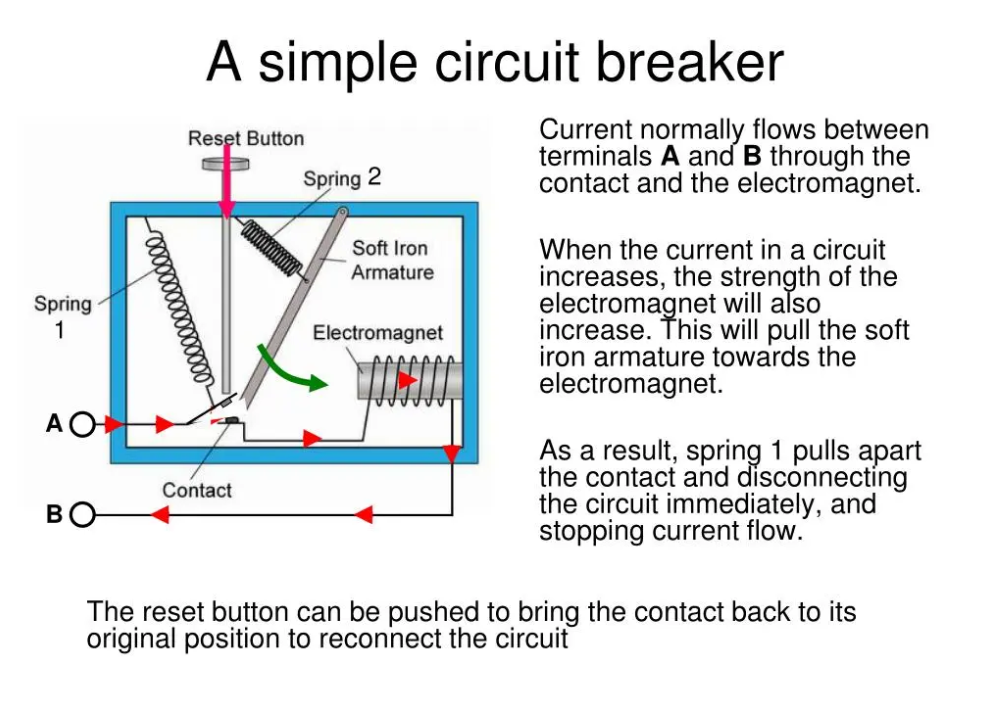
How does it Work?
As you can see in the diagram, Spring 1 usually pushes down on the switch at the point of contact, along with the soft iron armature, completing the circuit and allowing electricity to flow through. However, if the current increases beyond the circuit’s maximum capacity, a fascinating thing happens.
Remember how, in an electromagnet, the strength of the magnetic field increases if the current increases? Well, obviously, in this case, the magnetic field strength increases. This attracts the soft iron armature, releasing Spring 1 and opening the circuit, causing it to “break” and prevent the flow of electricity!